Metal Lathe Maintenance
Daily Maintenance
A lathe should be oiled daily/every time it is used. This video is a good general guide:
Before Starting
1 General Inspection
Take off the blue cover.
- Is anything out of place Is anything missing or broken?
- Check behind and around the machine.
- Check that the Rotary converter is plugged directly into the wall and not into the budget extension lead (It's a high power device.)
2 Check the Oil Levels

Check the 3 oil sight levels the headstock, feed gearbox and apron, they should be between midpoint and top. If they look all yellow, that’s fine, you are looking at the oil, they are slightly over full.

In the highly unlikely case that they look completely white or there is a large puddle of oil. That is not good! If the oil levels are low, then starting the machine could do a lot of damage, check for any leaks. Instructions for topping them up are lower down this page.
3 Check the Lathe is Clean & Oily
Check are ways, carriage and chuck clean and oily? If they are not, this means the previous user was a spanner, and expect you to tidy up after them. Please clean the ways and lubricate the 9 points before you use the machine. Move all the slideways, check they move freely and the ways are clean under the carriage.
4 Test Start the Lathe
Check the lathe is in gear at a sensible speed, then start the machine. Observe if there are any funny sounds/sights/smells.
If anything seems wrong or unhealthy, please stop the machine and either investigate or report on the forum and put a sign on the machine - This will prevent small problems becoming big problems. If you have any doubt, please ask, other members are happy to help.
Post Use - Routine
1 Cleaning

Always leave the machine clean and safe, and in a better state than you found it. Useful tools, are the dustpan and brush under the lathe, shop vac in the CNC room, blue roll (consumable) and the long handle swarf pliers.
- Put all the tools and accessories away in the drawers or in their holders on the back shelf.
- Clean and wipe down the external moving parts of the machine, the carriage, cross slide, and tool post.
- Pay particular care to clean and wipe down the ways. Check and clean away any coolant or swarf under the carriage and the tailstock, by moving these out of the way.
- Clean the very nice and expensive chuck.
- Clean out the swarf tray, removing all swarf, chips and coolant. If you did use coolant, you will need to clean out all the coolant from the tray.
- Clean floor around machine. You may need to use the emergency spill kit on corner of bench if there were oil or coolant spills.
2 Lubrication
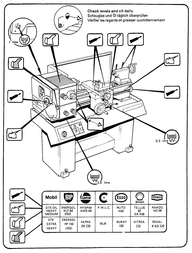
This is the diagram from page 8 of the lathe manual showing the oiling locations.
You can’t really over oil a lathe. It must have the correct types of oil used in the correct locations.
The small plastic oil can that lives on the lathe contains “ways oil” or more formally type 1 Slideways Oil ISO 68. If it is empty, please fill it up, spare Slideway Oil is in the COSHH cupboard. Put 1 squirt of oil into each of the 9 oil nipple points shown on the diagram. They are on the carriage, compound slide, lead and feed screws, tailstock and under the headstock cover.
Wipe a small amount of oil on the chuck, the ways and any other bits of bare metal that look like they might be thirsty.
3 Finishing Up
- Turn the lathe off and replace the padlock.
- Turn off the rotary converter, lamp and DRO.
- Replace dust covers.
- Report any issues, anomalies or breakages to the forum.

Lubricant Store
In the Yellow COSHH Cabinet there are three 5 Litre plastic bottles of oil. Under the lathe there is a small plastic funnel for pouring these oils.
- Type 1 Slideway Oil ISO 68 - “Ways Oil” use this to top up the small oil cans and to lubricate the ways as well as the gearbox and the apron reservoir.
- Type 2 Machine Oil ISO 220 Vitrea 71 72 73 - This is for the lead screw gearbox which is the bottom half of the headstock. the filler cap for this is on the left end of the headstock under the cover.
- Type 3 Hydraulic Oil ISO 68 - In the paper copy of the manual manual there are 3 oils recommended, This oil is only for the filler cap in the top of the apron. In later PDF versions of the manual only the 2 oils above are recommended, so when this is used up we do not need to replace it.
If these are used up, they are on the consumables list and can be ordered from Westway Oils.
Specific Maintenance from the User Manual
Below is reproduced from the M250 Lathe Manual, hence the arcane language.

Changewheel Shear Pin
(Fig. 1) A protection against accidental overload in the end gear train is provided in the form of a shear pin fitted in the splined sleeve on the top change wheel shaft. In the event of replacement being necessary a 4 mm (5/32“) diameter x 20 mm (3/4”) long mild steel pin should be fitted as follows:
- Remove the hexagon nut, washer and change wheel,
- pull off the splined sleeve and remove the broken pin parts from both sleeves and shaft.
- Fit new pin. NOTE: The pin acts in single shear and will only enter the sleeve from the 'big-hole' side.
Leadscrew Shear Pin
(Fig. 2 ) A shear pin device is incorporated on the leadscrew adjacent to the gearbox, as protection against overload. Instructions for replacing the shear pin are as follows:-
- Remove the torque limiter cover plate.
- Disengage shear pin assembly by sliding away from gearbox face.
- Rotate spring steel cover on its locating sleeve until access slot is exposed.
- Release M5 dog-point set screw in sleeve and rotate sleeve and cover until shear pin is exposed through slot.
- Replace shear pin as shown in illustration (2) and re-assemble ensuring that the dog point of the M5 set screw is correctly located.
Drive Belts
(Fig. 3 & 4) Access to the Drive Belt is gained by removal of the moulded end guard when vee Belt tension may be assessed by applying finger pressure on the belt at a point midway between the two pulleys (fig. 3). For correct tension a deflection of about 10 mm should be possible.
To adjust the vee belt tension - release the lock nut on the adjusting screw (fig. 4) to increase tension, tighten screw against the bed until correct tension is obtained then re-tighten lock nut.
It is important that when making adjustments a straight edge be placed across the face of each pulley to ensure that correct alignment is maintained.
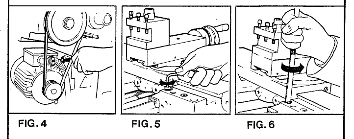
Saddle Strips
(Fig. 5 & 6) Wear on the rear and front saddle strips may be accommodated by adjustment of the retaining sleeves located in the top face of the saddle; two for the rear and one each for the two front strips. The procedure for adjustment is to first release the socket head screw, slightly turn the slotted head sleeve anti-clockwise and then re-clamp the cap screw. Care should be taken to avoid over adjustment; a 30° turn at the sleeve represents approximately 0.1 mm ( .004“) take up in the strip.
Tailstock Bed Clamp
(Fig. 7) The angular lock position of the bed clamp lever is adjusted by means of the self-locking hexagon headed bolt located on the underside of the tailstock and between the bed ways.
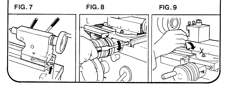
Cross-Slide
(Fig. 8) Wear on the taper-gib strip may be adjusted for by clockwise rotation of the slotted head screw on the front face of the cross-slide. The procedure being to first slacken the similar screw at the rear then re-tighten this after adjustment to clamp the strip in its new position.
Top Slide
(Fig. 9) Take up for wear on the top slide strip is by means of the four (self-locking) socket set screws in the front face of the top slide casting.
Cross-Slide Nut
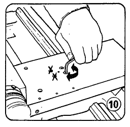
(Fig. 10) Provision is made for the elimination of backlash in the cross-slide nut, the procedure for adjustment being as follows:
- Release only the rear pair of socket cap head screws in the top face of the cross-slide, which allows a spring loaded device to automatically remove backlash.
- Re-tighten cap head screws.
Spindle Bearing
The spindle bearing assembly is carefully set before despatch of the lathe from our works which should ensure a high standard of performance without the need for further attention. (There is more about this in the manual PDF.)