Wood CNC - Shapeoko 3 XL
Induction Required
This equipment requires an induction prior to use. For your own safety and to avoid damage to the equipment do not attempt to use it until you have been inducted.Crush and flying debris Hazard
Keep fingers away from moving parts. Risk of flying debris (e.g. tool crash).PPE Required
This equipment requires the use of hearing protection during use, and finger protection when changing bitsIntroduction
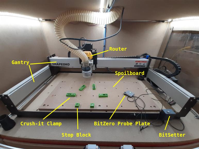
Our CNC Router is a Shapeoko 3 XL.
The router has a usable bed size of 800mm X 350mm.
We have 1/4“ and 1/8” collets for the router, and a small collection of bits for basic operations. For anything more complex (or to guarantee a sharp bit) you should use your own router bits.
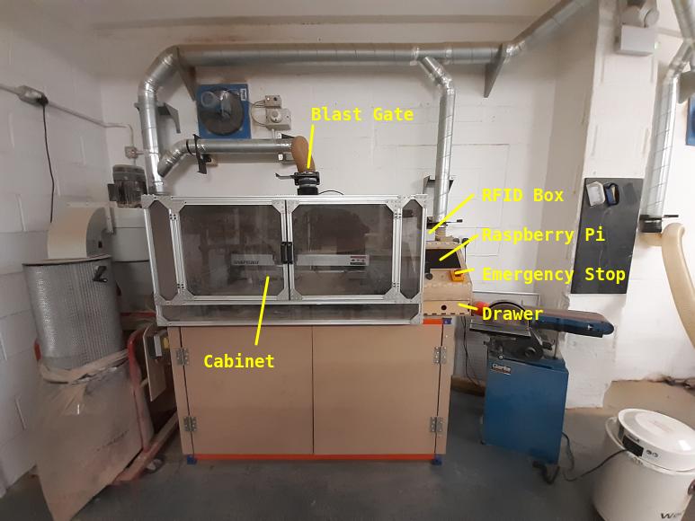
The router is driven using Carbide Motion, which is loaded on the Raspberry Pi the wooden box beside it.
The router is protected by an online induction. To get inducted, read this page carefully, then take the quiz on the membership system.
This wiki page will explain the basics of how to safely set up and run a simple job on the router. It will not teach you how to design things for the router, prepare files for cutting.
To learn more about the router, including how to design and prepare files for it, check out these videos by the manufacturer:
- Carbide3D Getting Started with CNC - A text and video series that will give you a simple introduction to the world of CNC.
- Carbide3D Jumpstart course - A text and video series that takes you through designing and making several projects.
- Carbide 3D YouTube Page - Contains a large number of helpful videos with guides and tips.
For first time CNC users, we recommend using the free version of Carbide Create to design and prepare your files, as this software comes pre-programmed with the parameters of our machine and our communial bits.
Parts and Layout
Permitted Materials
You can work with the following materials on the CNC router:
- Hard wood
- Soft wood
- MDF
- Plywood
- Acrylic
- Delryn
You must NOT work with these materials:
- Metal
- Humans
Usage Insturctions
1. Pre-Useage Checks
Before you use the CNC Router, it's important to open the cabinet doors and check the following:
- That the drive belts look in good condition, with no cuts of frays.
- There is not a thick dust build up on top of the big silver gantries.
- That there is nothing inside the enclosure that could interfere or jam the movement of the router.
You also need to check that:
- The fire extinguisher is present in the woodshop.
- The dust collector bag is not full.
If you see anything wrong with the condition of the machine, don't use it and let the committee know on the forum.
2. Starting the Machine and Software
- Log into the machine with your card/fob (once you've passed the induction). The enclosure lights should turn on when you log in.
- If the Raspberry Pi is not already running, press the silver power button to boot it up. Note that the screen may not immediately respond when you press the button.
- If the emergency stop button has been pressed, rotate it clockwise to reset it.
Once the Raspberry Pi has booted:
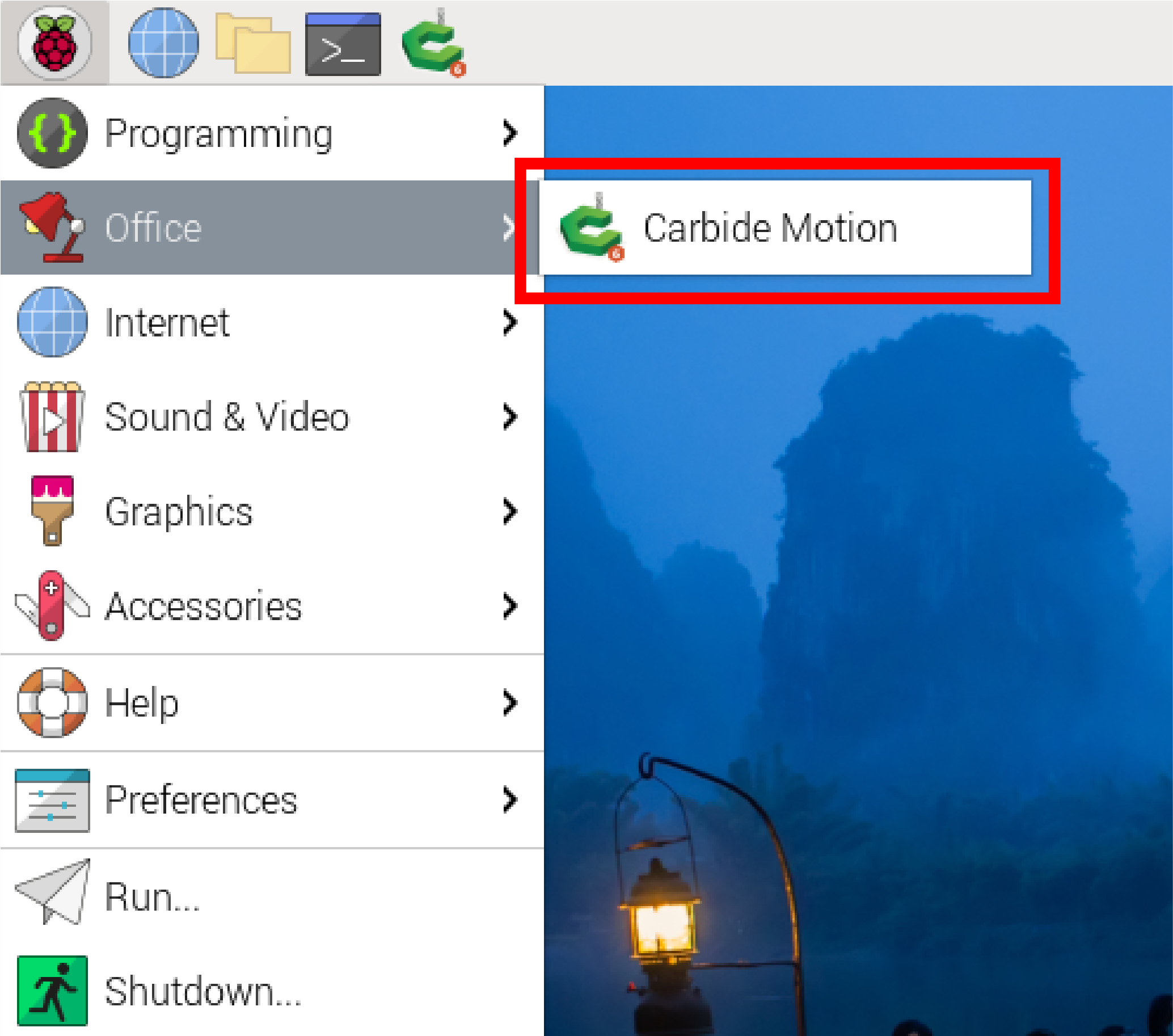
- Start the “Carbide Motion” software by pressing the raspberry button in the top left of the screen → Office → Carbide Motion.
- In Carbide Motion, press the “Connect to cutter” button
- Press the “Initialise Machine” button.
The router will now move to the rear rightmost point, and will then move to the front right.
3. Clamping Down your Stock
NOTE: All items for the CNC including probe pins, router bits, collets spanners and allen key can be found in the small draw under the Raspberry Pi and returned here after use.
*Before you clamp down your stock, move the router out of your way:
- Press the “Jog” button at the top of the Carbide Create window to open the Jog Screen.
- From the Jog Screen, use the buttons on the screen or the USB pendant to move the router out of your way.
- Place your stock on the spoilboard. Use the small “stop blocks” on one side to position your stock and align it with the grid of holes.
- Use the Crush-It clamps on the opposite side of your stock to hold it securely. To do this. first loosen (but don't remove) the small screws on the front of the clamps, position the clamps tightly against your stock, bolt the clamps to the spill board, then tighten the front screw to push the clamp face firmly against the stock.
- Double-check that your stock is firmly attached to the spillboard by trying to move it. If there is any movement, you should re-clamp it.
Tip: The stop blocks have smooth and serated sides, and the Crush-It clamps have replacable smooth and serrated jaws. The serrated surfaces give better grip but can leave marks on some stock.
Tip: Make sure the clamps don't block your toolpath!
Tip: Use bolts of the correct length to fix the clamps to the spillboard. If the bolts are too long they will bottom out in the threaded holes.
4. Probing your Stock Location
We have a BitZero probe kit, which we use to accurately locate corner of your stock is and how tall it is. This is known as setting the “Work Zero”. The kit consists of a probe pin, a probe plate, and a magnetic earth connection. To use the BitZero:
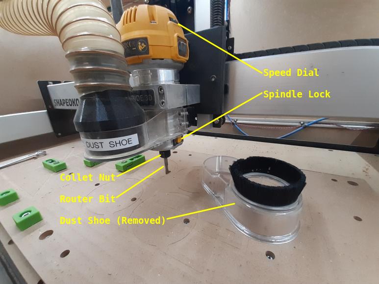
- Remove the dust shoe (it's magnetically attached and just pulls downwards)
- Install a probe pin into the router collet (using the instructions for installing router bits and probe pins at the bottom of this page).
- Place the probe plate on your stock so so that is tight to the front left corner.
- From the Jog Screen, use the buttons on the screen or the USB pendant to position the router so that the tip of the probe is within the circular hole in the probe plate.
- Attach the magnetic earth to the router collet.
- From the Jog Screen, press Probe. A pop-up window will open.
- Press “Corner” then on the next screen, press “Begin Probe”.
The router will move slowly to identify the sides of the circular hole with the probe pin, then it will lift out of the hole and tap the top of the probe plate.
When it has finished doing this, a pop-up window will ask you to remove the magnetic earth.
- Remove the magnetic earth from the router collet.
- Press the Ok button.
The router will now move to the front-right and touch the probe pin to the height probe on the machine's frame. This completes the probe operation.


5. Loading your File
- Insert your USB drive into USB port on the front of the Raspberry Pi case.
- Cancel the “Removable Medium” pop-up menu.
- Press “Run” at the top of the Carbide Create window to open the Job Info Screen
- Press “Load New File” on the Job Info Screen.
- In the Open File pop-up, navigate to your USB drive (computer → / → media → cncuser → your USB drive) and open your .C2D file.
Tip: You can sanity-check your file is correct by switching to the Top View tab.
6. Starting your Job
- Press “Start Job” on the Job Info Screen.
- On the pop-up, press “Start”
The spindle will now move to the front-right, and a new pop-up will ask you to install your first bit.
- Install your first router bit into the router (using the instructions for installing router bits and probe pins at the bottom of this page).
- Re-fit the magnetic dust shoe.
- Switch on the dust collector.
- Open the blast gate for the CNC router, and close the blast gates for any machines that are not in use.
- Close the cabinet doors.
- Press the “Resume” button on the pop-up.
The spindle will now spin up, and a new pop-up will ask you to check the speed setting on the router.
- Check the speed dial on the router matches the requested speed in the pop-up.
- If it doesn't, open the cabinet doors, change the speed, and close them again.
- Press “Resume”.
After a brief pause, the job will begin.


7. While the Machine is Running
The machine MUST be closely supervised at all times when running. This is to ensure:
- The workpiece remains firmly clamped
- The machine doesn't jam or get stuck
- The extraction is clearing dust effectively
- There is no risk of fire
Opening the door during the job will pause the machine and show a pop-up. To resume the job, close the doors and press “Resume” on the pop-up. This is useful if you need to check your clamps or remove detritus.
Hitting the E-stop button during the job will kill the power to the controller and spindle.
8. Changing Bit During a Job
Some jobs require more than one bit to complete, and you will be asked to change bits partway through.
When this happens, the router will move to the front-right of the cabinet and spin down. A pop-up will ask you to install the new bit and then set the new speed in exactly the same way as you did for your first bit at the start of the job.
9. After your Job
When you're finished, you should always:
- Clear any waste or debris from the cabinet.
- Log out of the machine by pressing the button on the RFID box.
- Shut down the Raspberry Pi if the machine isn't going to be used again soon.
How to Change Router Bits or Probe Pins
The cutting edges of bits can be sharp so gloves should be worn when changing bits.
To install a router bit or probe pin:
- Remove the dust shoe.
- Hold the yellow button on the side of the router and use a 17mm spanner to loosen the collet nut.
- Once the collet is loose, you can withdraw the bit or pin currently installed.
- We have a 1/4“ and 1/8” collet, to suit different bits. If you need to swap to the other collet:
- Continue to unscrew the collet nut until the collet and nut can be removed from the router.
- Screw the other collet and nut into the router in it's place.
- Insert the new bit or pin into the collet.
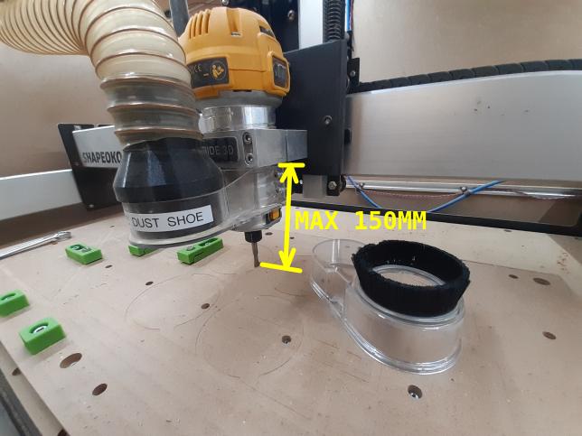
- Make sure that the bottom of your bit or pin does not protrude more than 150mm below the bottom of the aluminum bracket that holds the router. There is a helpful L-shaped guide in the drawer to assist when measuring this.
- Hold the yellow button on the side of the router, and use a 17mm spanner to firmly tighten the collet nut.
Glossary of Common CNC Terms
Most definitions here are adapted from Carbide3D’s video series, with small changes for our machine and accessories.
Tip: These are the basics you’ll need for your induction quiz. Links to the original videos are at the bottom if you want to go deeper.
Core Concepts
CNC – Computer Numerical Control
A computer-controlled machine that moves a cutting tool with high precision. Our laser cutter, 3D printers, and vinyl cutter are also CNC machines.
CAD – Computer-Aided Design
Software used to design your part. You draw shapes, add features, and prepare them for cutting.
- We use: Carbide Create (free version is fine)
- Why it matters: This is where you create the geometry of your project.
CAM – Computer-Aided Manufacturing
Software that converts your CAD design into movement instructions for the CNC.
- We use: Carbide Motion (pre-installed on the workshop Raspberry Pi)
- Why it matters: This is the “translator” between your design and the machine.
G-code The text-based “language” CNC machines read. Generated automatically by CAD/CAM software. You don’t need to write it manually.
Machine Movement
Axes
- X: Left ↔ Right
- Y: Front ↔ Back
- Z: Up ↔ Down
Tip: Y has the “Y rails” and Z is the vertical axis — that leaves X as side-to-side.
Home Position – The fixed point the machine returns to after startup.
Work Zero – Your chosen starting point for a specific job (usually a corner or centre of the stock).
Design Files
Vector Graphics
Drawings made of lines and points (e.g., SVG files). Ideal for CNC because the machine can follow their coordinates exactly.
Toolpaths
The routes your cutter will follow. Defined in CAD, turned into G-code in CAM.
Materials & Workholding
Stock – The material you’re cutting.
Spoilboard – A sacrificial board under the stock to protect the machine.
Workholding – Clamps or other methods to secure your stock so it doesn’t move.
Cutting Parameters
Feed Rate – How fast the cutter moves through the material (X/Y).
Plunge Rate – How fast the cutter moves down into the material (Z).
Spindle Speed – How fast the bit spins (RPM), adjusted on the router dial.
Why it matters: These three settings determine cut quality and safety. Carbide Create has safe starting values for common materials.
Tools & Cutters
End Mill / Bit – The cutting tool.
- Flat End Mill – Flat tip, general-purpose cutting.
- Ball End Mill – Rounded tip, for 3D contours and smooth finishes.
- V-Cutter – Angled tip, ideal for engraving and sign work.
- Fly Cutter – Large flat cutter for surfacing spoilboards or material tops.
Flutes – The cutting edges on a bit. More flutes = smoother cut, fewer flutes = faster removal.
Upcut / Downcut – Direction of flute spiral:
- Upcut: Pulls chips up and away (better chip removal, but can lift stock).
- Downcut: Pushes chips down (better surface finish, but can trap chips).
Shank size – the size of the diameter of the solid part of the bit, two sizes are currently supported by our router:
- 1/8 - 1/8 inch (3.175mm).
- 1/4 - 1/4 inch (6.35mm).
Machining Types
2D Machining – Cutting shapes at a constant depth.
2.5D Machining – Multiple depths, but cutting one flat layer at a time (e.g., pockets + cutouts).
3D Machining – Machine moves in X, Y, and Z simultaneously to create complex curves.