Router Table - Triton RTA 300
Self-Induction Required
This equipment requires an self-induction prior to use. For your own safety and to avoid damage to the equipment do not attempt to use it until you have completed this.Entanglement Hazard
This equipment is hazardous to the user or those around them, take care during use.PPE Required
This equipment requires the use of eye protection and hearing protection during use. Respiratory protection is recommended. Gloves must not be worn.

Risks
The table router is hazardous to the user and those around them. It is therefore is covered by an induction and RFID lockout to ensure it is only used by inducted users.
PPE is required, users should wear eye protection, hearing protection and respiratory protection during use and this should be offered to others in the area.
The fixed or manual extraction system must be used.
This equipment is an entanglement hazard, please remove loose clothing, jewellery and remove other objects from the workspace that could get caught or ejected.
After completing any routing the area must be cleared of spare wood, dust and debris.
Full risk assessment can be found here: [TBC]
Please also refer to the generic electrical and manual handling risk assessments (table weighs 12.5kg)
Induction
Due to the risks to users and others this equipment has a mandatory online induction. Go to the Membership Portal PC to sign in and find the online induction. Once completed your card/fob will be authorised to unlock the RFID lockout box so the equipment can be switched on.
Specification
Manuals
The information below has been taken from the manual and modified to match the accessories, risk assessments and safety requirements of Bristol Hackspace.
Accessories
- Bits - Stored on the shelf under the wood working table
- Biscuit Jointer - Stored behind the beam to the left of the Router Table and behind the pillar drill


Missing Accessories include a protractor for angled work
Introduction
 These 3 links give an overview of the capabilities and basic use of a router and table.
Router Table Basics - A Quick Tour of Router Table Techniques
Router Table Tips and Techniques
Setting Up and Using a Router Table - A Woodworkweb.com Woodworking Video
Dust Extraction
- The router table must be connected to the Hackspace extraction system or the woodshop vacuum until this is installed. This must be switched on before use.
- If using the workshop vacuum - firmly plug the wand of the woodshop vacuum into the tapered hose adapter as in picture to the left
- Ensure shavings do not build-up between the fences and your workpiece. Brush or blow away accumulated shavings after every few cuts, when the cutter has stopped spinning completely.
Standard configuration
The standard set up should have the fence, guards, pressure fingers in place and therefore these should be checked before use. Shown in picture to the left.
Check the fence, guards and pressure fingers
Check Fence Squareness and Position
See Fig 14.
- Use a set square against the face of the fence to check it is square to the table. If necessary loosen the horizontal locking screws through the rear flange of the fence and adjust the vertical jacking screws in the braces until the fence is square, then re-tighten the locking screws
- Adjust the two front braces together then the two rear braces together

Position when in use:
- The MDF faces should always be positioned as close to the cutter as possible. Position them by sliding forward or backward
- Ensure they are tensioned firm enough to resist unwanted movement. For very heavy or difficult cuts lock the faces by fully tightening the screws
- Fit the Fence Brackets (38) to the inner holes of the MDF Fence Faces using the M4 x 25 Countersunk Screws (40) and M4 Nyloc Nuts (39)
- Insert the Front Guard (37) into the tracks on the rear guard. Some initial force may be necessary. Loosen the knob and slide the guard guide forward until the front guard can be fully lowered and the guard slides against the MDF, then tighten
- Loosen the round knobs and fit the fence to the table via the T-bolts through the table slots. The T-bolts are designed to pass through the table slots and then be turned through 90°, locking the fence to the table when the knobs are tightened
- The fence is held square by four adjustable braces
Check pressure fingers position
- Insert two Finger Posts (52) with Spacers (50) through the holes in the fence brackets and fit the Plastic Washers (51)
- Insert the Bent Pressure Fingers (49) through the slots and tighten the knobs on top of the finger posts to tension them into position
- Insert the remaining two finger posts through the preferred holes in the sliding insert, then fit the washers and Straight Fingers (48) before tightening
- The finger posts with spacers can also be fitted directly to the holes in the table for operations such as ‘Planing to Width’. The finger post spacers should be reversed when fitting to the table
- The bent and straight pressure fingers are interchangeable depending on the operation you are performing

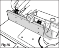
Changing Router Bits
NOTE The tool for raising and lowering the collet is currently broken or missing - 26-01-2025
1/2" and 12mm Collets
Tools required:
- 24mm Spanner - only use the router spanner or a 24mm open ended spanner. Not an adjustable spanner, not grips, not any other system
- Tool for adjusting the height of the collet
Steps
- There is an interlock that prevents the collet being lifted above the table whilst the router is switched on. Therefore before the collet can be lifted above the table this switch must be “off”, this can be found on the left of the router motor under the table.
- There is a switch on the router motor behind a transparent slide, switching it off will allow the transparent switch cover to slide closed, disabling in the safety interlock. This is under the table on the same side as the fence normally is.
- Use either the handle/tool in the socket indicated in the video or the main raise/lower controls on the router motor to raise the collet up
- The collet should lock (i.e. not be able to rotate) once the collet is raised above the router table
- This is an additional safety to ensure the router cannot be switched on when changing the router bit
- Loosen using the 24 mm Spanner
- Put in router bit
- Tighten using the 24 mm Spanner
- Lower collet
- Remove the handle
- Once the bit has been changed and the collet is below the table (and therefore able to rotate), slide the clear safety cover across the switch on the router motor back and switch it on
- the lockout box can now be tapped to enable the machine


Tips
- The main calibration scales on the table are for reference only. They do not relate to any actual dimensions, which are determined by the diameter of the cutter used
- Unlike the saw’s rip fence, the router fence does not have to be locked parallel on the table. The readings in both fence windows may differ
- Wherever possible use both side pressure and down pressure fingers. When they cannot be used ensure the workpiece is pressed down on the table and against the fence during the cut
- It is always best to do a test run first on an offcut of the material you will be working with, to ensure the desired cut is achieved
- When using narrow cutters or when working on small components, slide the MDF fence faces toward each other until they just clear the cutter. This provides maximum support for the workpiece, close to the cutter (Fig 16)
- When using cutters larger than 25mm (approx. 1“) diameter and less than 50mm (approx. 2”) replace the small table insert with the larger size ( this is currently missing but there is an alternative in the biscuit joiner box)

Key Factors For Quality of Cut
The quality of cut using a router depends on a number of key factors.
The Feed Rate
- Don’t overload your cutter. Take into account the size of the motor, cutter size and type, depth and width of cut, and the type of material
- Too rapid a rate of feed will cause the router to overload. Cutting will be difficult to control, and tear out (splintering) is likely. Damage may occur to your router motor or chuck, and in extreme cases the cutter could break
- On the other hand, too slow a rate of feed will cause the bit to rub instead of cutting. This will show up as burn marks on your workpiece
- Practice will determine the optimum feed rate. The cut quality, and the sound of the router motor are guides to the correct feed rate
- Avoid pausing during the cut; this will risk developing a slight burn mark or step in your work
- It is always best to first do a ‘trial run’ with the power off to ensure that you can complete the cut smoothly without obstruction
Depth of Cut
As a general rule:
- For small, straight cutters (up to 10mm / 3⁄8“ in diameter) ensure that the depth of cut does not exceed the diameter of the bit
- For larger diameter bits, it is generally better to make two or three shallow cuts rather than one deep cut
Router bit selection
- Routers operate at free-running speeds of between 18,000 and 24,000 rpm (min-1)
- Sharp cutters are essential for clean cuts, free of burn marks and tearout
- We do not recommend high speed steel bits because they generally do not retain their sharp edges for long
- From Manual. We recommend that you purchase tungsten carbide tipped router cutters. Tungsten carbide is the hardest commercially available cutting edge material
- When profile cutting or edge trimming, look for bits which have a ball bearing pilot on top. Bits which have an integral pilot (i.e. no ball bearing race) can burn or mark the work
- Bits can be found in the bits for the Router table on the shelf under the wood working table, see images above under accessories
EDGE REBATING
- Edge rebates are generally performed using a straight cutter. If using a bearing guided rebate cutter, refer to ‘Edge Moulding’
- Always fit the router fence when edge rebating
- Start by setting the router fence flush with the cutter
- Use a wooden straight edge along the fence face and rotate the cutter until its cutting edge is in the outermost position
- Adjust the fence until the front and rear scale readings are similar and the straight edge is touching the cutter, then lock the fence

- When rebating to match the thickness of a component (eg. a cabinet backing), use an offcut of that component to set up the cut as follows:
- Set and lock the router fence flush with the cutter
- Install the micro-adjusters in the table slot behind the fence but do not yet tighten them into position
- Place your offcut between the back flange of the fence and the micro-adjusters then tighten them into position (Fig 18)
- Remove the offcut, re-position the fence back against the micro-adjusters and lock it

- When rebating to a required dimension, use the fence scales as a reference or use the micro-adjusters as follows:
- Set the router fence flush with the cutter
- Screw the thumbwheels on the micro-adjusters out to provide sufficient adjustment
- Tighten the micro-adjusters in position against the rear of the fence and screw the thumbwheels in to obtain the required rebate amount. One complete turn is 1.0mm and calibrations are marked every 0.2mm. (1⁄32” = 0.8mm, 1⁄16“ = 1.6mm, 1⁄8” = 3.2mm, 1⁄4“ = 6.4mm)
- Unlock the fence, move it back against the microadjusters and re-lock
- For short edges, the fence should only be used to set the rebate depth; use the protractor to guide the workpiece- currently missing (See ‘Cross-trenching’). The fence must be set exactly parallel for this operation
TRENCHING
WARNING: For many trenching operations, the cutter cannot be guarded. Keep your hands well clear and never trail your fingers behind the workpiece
Trenching against a fence
- For trenches up to 100mm (4”) in from the edge of a workpiece, the router table fence can be used
- Set your router to the desired rebate depth and lock your fence at the required setting. Feed the workpiece smoothly through the cutter and against the fence, whilst keeping it pressed down evenly against the table
Cross trenching is currently not possible on this equipment as the protractor is missing
PLANING
- Planing cuts should be performed with the cutter mostly hidden behind the fence faces
WARNING: NEVER make planing cuts with the workpiece passing between the cutter and fence on the right. The cutter will flex aside, ‘climb up’ on the work, and rip the workpiece out of your hands - or pull your hand into the cutter
Planing on the router fence

- Planing cuts of 0.5, 1.0, 1.5 & 2.5mm can be performed using combinations of the 1.0 & 1.5mm planing shims supplied
- You can use your own shims to achieve other planing cuts
- Push the spring-loaded MDF face away from the fence and slot the shims into the gap created, straddling each set of screws (loosen spring tension if necessary)
- For 1.0, 1.5 or 2.5mm planing cuts, fit the appropriate shims behind the rear MDF fence face
- For 0.5mm cuts, fit the 1.5mm shims behind the rear MDF fence face and the 1.0mm shims behind the front MDF fence face
- Use a wooden straight edge to align the cutter blade with the rear MDF fence face (Fig 26), then begin your cut
Planing a high face on the router fence
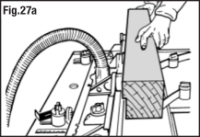

- For high face work, remove the front guard and position the guard guide back behind the fence. The pressure finger assemblies must also be removed from the fence
- High face cuts require two passes:
- For 1.0 & 1.5mm cuts, insert the appropriate shims behind the rear MDF fence face
- Lock the fence with the rear face aligned with the cutter
- Remove the shims and, without re-adjusting the fence, complete the first pass (Fig 27a)
- Re-fit the shims behind the rear MDF fence face, then flip the workpiece and complete the second pass (Fig 27b)
- Note: for 0.5mm high face planing cuts, use your own 0.5mm shims behind the rear MDF fence face
PLANING TO WIDTH
- When planing to width, remove the router fence and relocate the safety guard onto the router plate
- To remove the guard, first adjust the MDF faces out to their furthest setting. Lift the red lock tab at the rear and depress the catch to remove the guard from the fence, then re-fit it to the table. Reposition the front guard back until it is flush against the rear guard
- Fit the side pressure fingers to the table holes with spacers reversed, as described in ‘Assembling the pressure fingers’ (Fig. 13)
- The straight pressure fingers should be fitted
- When planing to width, you must use a fence on the left side of the cutter (viewed from the switchbox end), therefore a Series 2000 Workcentre, Extension Table or planing jig is required – see guidance for each below
- Small planing cuts provide a better result. Aim for less than 3mm (1⁄8“) with each pass
Using a planing jig
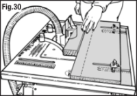

- To make a planing jig, cut two boards from 19mm sheet material to fit perfectly within the table slider opening
- Rebate the edges of one board (the base board) to accommodate the slider tracks and ensure the jig sits flush with the table
- With the router fence set at maximum width, make a slot in the base board using a 1⁄2” (12mm) dia. straight bit. Slot a little over half way through the board then flip it and make a second slot in the same face
- Use the same method to make slots in the other board, but this time using a 1⁄4“ (6mm) dia. bit
- Fit the jig base to the table and use the router fence clamping knobs and T-bolts to join the top to it
- The full range of adjustment can be achieved by rotating the jig base and/or the jig top
- Place the workpiece between the cutter and the jig and lock the jig
- Remove the workpiece and reset the jig top towards the cutter by the desired planing amount
- Depending on the position of the jig you can use the micro adjusters in the jig slots to set the width, either by using the thumbwheels or the fence shims, as described in ‘Planing’
- To increase the useful range with the micro adjusters, the jig fence can be replaced with a narrow batten (Fig 31)
EDGE MOULDING
- Decorative cutters commonly have a ball bearing or plain pilot on top, which can be used without a fence. However, straight sided or slightly convex workpieces are more easily edge moulded using the fence
- For concave or complex shapes remove the fence and fit the guard to the router plate
Using the router fence
 It is always best to use two or three shallow passes rather than one deep pass to lessen the chance of tearout or splintering
Adjust the fence to just expose the cutter for the first pass. Progressively expose more of the cutter by adjusting the fence between passes until the final pass when the pilot should be level with the fence
For extra support and guidance, short edges are best performed against the protractor (see ‘End Grain Work’ below)
Free-hand edge moulding
 WARNING: Never attempt free-hand routing without a bearing or pilot guided cutter
- Always use the guard as it makes the job safer; the integral lead-in and trail-out guides also make the job much easier
- Several passes are better than one deep pass. Start with the cutter lowered and progressively increase the cutter height for each pass
- Rest the workpiece against the front (lead-in) edge of the guard and maintain this contact while feeding the workpiece onto the cutter
- Continue the cut against the cutter’s pilot guide
- Near the end of the cut, swing the workpiece toward the rear (trail-out) edge of the guard
- Complete the cut with the work in contact with the rear edge of the guard
END GRAIN WORK
Currently not possible as we do not have a protractor
- Short edges, typically end grain, are not easily controlled against the router fence and can often tearout at the completion of the cut. This can be overcome by using the protractor fitted with an extended wooden face as described in ‘Cross-trenching’
- End grain work using the protractor can be performed with the fence fitted (see ‘Edge Rebating’), or with the guard fitted to the router plate (Fig 34)
Using a template guide

- Use the guard in the table mounted position whenever possible. If the guard cannot be fitted, due to the nature of the cut, take great care with your hand positions
- Templates are very useful for cleanly finishing the edges of curved or shaped components
- Template routing is achieved using a flush trim bit with top bearing (as used for laminate trimming)
- The fence cannot be used in this operation so the guard should be re-located to the router plate
- First, rough out the shape of the workpiece with a jigsaw
- Then, using tacks or double-sided tape, attach the template to the top of your workpiece
- Set the height of the flush trim bit so that the bearing runs only along the template. The workpiece will then finish exactly the same size as the template
- Feed against the direction of rotation, keeping both hands on top of the workpiece and well clear of the cutter
MORTICING
WARNING: The cutter cannot be fully guarded when morticing so ensure your hands are well clear of the cutter at all times and hold the workpiece firmly.
- You can cut mortices to house the stub tenons cut with your saw in the Workcentre.
- Most mortices will require the front guard and hold-downfinger assemblies to be removed from the fence, and the guard guide adjusted back behind the face of the fence
- Position and lock the fence assembly so that the workpiece will be in approximately the right position above the cutter
- Test the position of the fence by plunging an offcut of your workpiece onto the cutter
- Do not set the cutter too high. It is always best to perform several cuts at increasing settings
- Slide the piece forward along the fence for a short distance. The cutter will tend to push the material away from the fence, so firm sideways pressure against the fence is necessary
- Consider using the jig described in ‘Planing to Width’ to hold the workpiece against the fence
- Re-adjust the fence if necessary and repeat the test until satisfied with the position of the mortice
- To establish the beginning and end of the mortice, it is best to work between two stop blocks clamped to the fence. If the workpieces are too long to use stop blocks fitted to the fence, replace the MDF faces with longer ones and fit the blocks to them (Fig. 36)
- With extremely long workpieces (where it is not possible to work between stop blocks) reference the mortice position by drawing lines on the side of your workpiece and aligning these with pencil lines drawn onto the table to indicate the position of your cutter
TIP: For finishing, it is easier to round off the tenons rather than chiselling the mortices square at the ends.
Clean up

- Leave the machine set up ready for profile cutting with the router bit set below the height of the table. Fence and non-return pressure fingers in place.
- Clean and dust free.
!!!REMEMBER TO LOG OUT ON THE RFID LOCKOUT BOX!!!
Maintenance
The maintenance thread for the router table on the forum is here. If any parts are broken or missing, please report these on the forum. and if you are able to them please also repair or replace these.
Known Issues
- Sometimes the plunge action get jammed
- This means that sawdust has got down the tube
- remove the black plastic cover on the top of the left tube and empty out the sawdust.